
FAQs
Products
Q. Customized RF Coaxial/Microwave Connector
For any customized connector, please provide the OD of each section on cable per below drawing and the impedance.
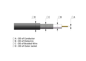
Your inquiry should specify the following, as applicable:
● Connector Interface or Series
● VSWR Requirements
● Insertion Loss
● Finish Requirements
● Hermeticity
● Mounting Method
● Frequency Range
● Specific Material Needs
● Mechanical Requirements
● Application
● Cable Requirements
● Back End Configuration
Q. How to choose the right RF coaxial connector?
To provide a quick and correct response from S-Conn, we need the following information before we quote.
1. What kind type of connector you need? (BNC, TNC or whatever)
2. What’s the terminating method? (Crimp, Clamp, Twist-on)
3. What kind of cable will be terminated? (RG58, 58 or whatever, please specify the brand)
4. Coaxial connectors are material-intensive. Please specify it if you can, or we quote it per economic or standard type for information.
5. How’ the impedance you need for the connector?
6. Do you have any special requirement for mechanical or electrical characteristic, such as frequency range, etc?
7. For cost and availability are always of paramount importance in selection connectors. If you can provide, will be much helpful to us.
Q. What’s the difference between U.FL and GSC?
GSC is usually terminated with ultra-thin FEP coaxial cables with OD 0.8mm. GSC and U.FL are made b Murata and Hirose respectively.
Currently it’s hard to offer a solution to make an interconnect together.
Q. Do you offer UFL - 7cm / 1.13 - GSC cable assembly?
GSC can be terminated only with OD 0.81mm cable. For 1.13 mm cable, HIROSE or I-Pex can be instead of Murata GSC connector.
Q. Are you manufacturing 75 Ohm 3GHz 1.0/2.3 connectors?
S-Conn offers a broad array of 1.0/2.3 connectors in either OEM or ODM to meet the demand from broadcast industry as High Definition is on top request to replace the current equipment.
Q.For metal parts, can you offer other materials except SUS303?
Normally we can cover it from 300 to 400 series. However, SUS303 is more easy to machine. Please advise the correct code, then we can check if it’s available on the local Smarket and offer it.
Q. About RoHS2 and REACH Declarations?
We can provide our self-declaration (CoC) to ensure our products are fully complied with RoHS2 and REACH.
Q. What is RoHS? Why do I need RoHS compliant products?
RoHS is the name for a directive passed by member nations of the European Union (EU) that restricts the use of certain substances in production of electrical and electronic equipment. Defined as the Removal of Hazardous Substances, this directive (2002/95/EC) specifically restricts six substances Lead, Mercury, Cadmium, Hexavalent Chromium, PBB and PBDE. This directive is sometimes referred to as the EU “lead-free” legislation, but is in fact more far-reaching.
If you wish to produce or sell electrical and electronic equipment in the EU after June 2006, then the products must be compliant with this ROHS Directive. Products that are not RoHS-compliant by this time will not be allowed to be sold in the EU.
Q. Does RoHS compliance mean lead-free?
RoHS compliance does not mean lead-free. The EU Directive defines certain content limits of the six hazardous substances, which vary according to the product being made and the hazardous substance required for its manufacture. For semiconductors, the main substance targeted for reduction is lead, which is found mainly in the external packaging.
Q. What is the difference between WEEE and RoHS?
WEEE stands for Waste of Electrical and Electronic Equipment and is also an EU law but it concerns the proper disposal of all electrical components after their useful life. RoHS is an importation restriction into the EU and WEEE is concerned with proper disposal of the equipment. Like RoHS, laws similar to the EU’s WEEE regulations are being evaluated in many countries. This set of regulations primarily involves product documentation and literature on proper disposal procedures.
Q. How does a point to multipoint system work?
A point to multipoint system uses one access point (AP) radio with up to 16 subscriber radios (SU) to create a multipoint network link extension. Each SU must be individually keyed to the AP before installation. After key exchanging the installation is simple, fast, and requires very little technical skill compared to other Ethernet products on the market today.
Each AP continually monitors the SU until data is transmitted or received. When data is to be transmitted either from the AP to the SU or vice versa the data is encrypted, transmitted, decrypted, and fed into the network.
Q. Can omni-directional and directional antennas communicate?
Yes, but please verify that the polarization and positioning of the antennas align properly.
Q. Can I protect the radio against lightning damage?
Yes, Lightning usually strikes the antenna and not the radio. To protect the unit if the antenna is struck use an AW-LA (Lightning Arrestor) to connect between the radio and antenna. S-Conn will not replace or repair a radio that is struck by lightning.
Q. What is the recommended antenna polarization?
Horizontal polarization is recommended because most RF noise in the unlicensed spectrum uses vertical polarization.
Q. What is a Yagi?
A Yagi antenna, also known as a Yagi-Uda array or simply a Yagi, is a unidirectional antenna commonly used in communications when a frequency is above 10 MHz.
Q. What is the difference between UHF and VHF antennas?
The most obvious difference between VHF and UHF antennas is the size and the applicable frequency.
VHF: Very high frequency. The radio frequency bandwidth of VHF ranges from 30 MHz to 300 MHz.
UHF: Ultra High Frequency. The radio frequency bandwidth of UHF ranges from 300MHz to 3GHz. Mostly used in short-distant telecommunication. The size of UHF antenna is smaller than VHF and has better gain.
Q. Can I install an antenna in my Attic?
Yes you can, but keep this in mind. One layer of asphalt shingles + roof felt + ¾” plywood roof deck = 50% reduction in signal strength. Plus if you have metal or aluminum backed insulation in the walls or under the roof the signal will be most likely blocked. You’ll have to remove the insulation or install the antenna in a different place. Although the antenna is inside, you’ll still need to make sure that the narrow end points toward the transmitter of the TV station.
Q. What is broadband?
This networking term has several definitions. The one most relevant to wireless networking is that Broadband, as opposed to narrowband, simply means more bandwidth. Broadband is faster than a dialup connection, or about 64Kbps to 45Mbps. Broadband is needed for wireless networking because of the fact that a broadband connection is “always on”, and therefore can be shared.
Q. Can I have more then one Access Point on my network?
Yes, multiple access points can be connected to a wired or wireless LAN. Most of the time, another access point will be added to include wireless connectivity in another part of the home or office. For homes with multiple floors, it is recommended that a repeater be placed on each floor to allow for better access throughout the home.
Areas are too large for coverage using one access point should try using repeaters or high gain antennas. This will increase the coverage area to allow for better roaming and wireless connection.
Q. Which antennas are compatible with D-link and Linksys devices?
Any 2.4 GHz antenna is able to connect to a 2.4 GHz D-Link or Linksys, or any other device with a removable antenna that operates at the 2.4 GHz range. Although the wireless devices have different connectors on them, we can adjust to the connectors by giving you the correct cable or pigtail to go from the antenna to the wireless device of your choice. Depending on the gain of the antenna, depends on how far you can run an antenna cable.
Q. Gain? Is it always needed?
The concept of gain in an antenna relates to the angle and spread of the pattern of radiated energy. The directivity of an antenna is the shape of its radiating pattern, in other words: the air space within which its transmitted signals can be picked up.
Gain is measured and quoted in Decibels (dB) relative to a reference antenna and is not a meaningful figure unless the reference antenna is stated. The industry standard reference antenna is a half wave dipole, (gain expressed as dBd).
Some antenna manufacturers prefer to use an isotropic antenna as a reference, (gain expressed as dBi). This is a theoretical antenna which does not exist; gain figures based on it will appear to be 2 dB higher than those referenced to the half wave dipole.
Q. I need a powerful antenna as my signal is very weak, how can I tell which of your antennas is most powerful?
The power of antennas are called Gain. Antennas with higher gain will produce the biggest improvements in signal strength. The antennas with the highest gain tend to be directional.
Q. What is the length range of your machined parts?
0.5mm~600mm is our capable length range, the length and tolerance usually depends on the outer and inner diameter of machined parts.
Q. How about the range of outer and inner diameter is in machined parts?
Outer diameter : 0.03mm~200mm
Inner diameter : 0.15mm~50mm
Q. What kind of material you can machine for parts?
Metal:
Brass, Stainless Steel, Aluminum, Titanium Alloy, Speed Steel, Alloy Steel and etc.
Plastics:
PTFE, POM, PE, PEEK and other materials.
If you have any other specification, inquiry will be the most welcomed.
Q. What equipment do you have in product inspection?
2.5 D Visual Measurement, Profile Projector, Micrometer, Microscope, Pin gage, Height Gage, Thread Gauge, Depth Gage, Vernier Calipers, Thread Plug Gauge,Thread Ring Gauge.
Q. How to terminate connector with RF assembly?
Terminating transmission lines with connectors requires various amounts of manual or automatic assembly. Most connectors are attached using combinations of soldering, clamping, and crimping.
Q. How to define the "Semi-Rigid Cables" ?
Semi-rigid cables offers the best shielding performance above any other cable assemblies. This type of cable assembly unbent or shaped with no electrical degradation according to customers specification. To assure proper installation into the applicable equipment we make steps in forming or bending of the raw stock which is normally straight into desired shape of configuration. Semi-rigid cable has an outer jacket (conductor) and a center conductor, separated by a Teflon-type dielectric. During the forming, the cable must be supported and the bend made preferably in a single motion to prevent deformation of the outer jacket.
Q.How to instruction the "Cable Assembly" ?
Please click “Cable Assembly Instruction” for intormation.
Q. What is MIM?
MIM is the acronym for Metal Injection Molding. It is an advanced metallurgical technology that integrates thermoplastic injection molding and conventional powder metallurgy technologies.
MIM is unique in that it realizes the mass production of complex three-dimensional objects with higher precision, greater design freedom and lower production cost.
MIM produces net or near-net shaped objects from a wide variety of metal materials.
The significant cost reduction provides MIM an obvious competition edge, particularly for small-sized and complicated-shaped parts required for high performance, over traditional methods, such as
● Investment Casting
● Machining & Screw Machining
● Die Casting when Steel rather than Aluminum or Zinc is desired
● Conventional P.M. (press and sinter)
Applications
MIM allows for molding small, intricate configurations precisely and economically. It is most suitable for volume production of complex and precise parts for industries of aerospace, automotive, medical, electronics, firearms, data storage, tool assembly and machine parts, and telecommunications.
The Future
This technology is currently being used by some RF coaxial connector makers for the production of RF connectors, particularly for telecommunication applications. Any inquiries on this cooperation is highly interested.
Q. MIM Advantages
As a relatively new technology, MIM brings about several benefits for metal forming.
● Applicable for a wide range of materials
● High degree of freedom for sizes and shape complexities
● Shortened product development cycles, eliminating or minimizing secondary machining operations
● Improved dimension precision
● Higher density through minimizing porosity
● Homogeneous distribution of chemical compositions
● Improve tensile strength
● Increase thermal conductivity
● Competitive pricing
Q. The MIM Manufacturing Process
Stage 1 :
Fine metal powders are combined with thermoplastic binders to form the injection moldable material.
Stage 2 :
The material is molded in an injection molding machine.
Stage 3 :
The green molded parts are processed to remove the binder and consolidate the metal powders.
Final Stage: The parts are through de-binding and sintering, then get the MIN Products.
Q. How to choose a right "Hand Tools for Coaxial Connector" ?
Please click”Hand Tools for Coaxial Connector” for information.
Q. How to choose the right material for RF connectors?
Materials used in a connector affect both cost and performance. Base metals include brass, beryllium copper, and stainless steel. Gold is the most common plating for the center pin because of its lower loss and corrosion-resistant interface. Silver or tin plating offer a lower-cost alternative. Although MIL-C-39012 requires silver plating for the housing, silver tarnishes, creating an unattractive finish. Many users prefer tarnish-resistant nickel or nickel alloy finishes.
Q. How to recognize the right part number for RF connector?
Please click “How to recognize the right part number for RF connector” for information.
Q. How to define the Plug and Jack?
Definition of Plug and Jack
Plug
A plug is a connector featuring the active part of the coupling mechanism (for example coupling nut).
Jack
A jack is a connector featuring the coupling mechanism complementary to the plug.
Q. How to define the "Connector Type" ?
STRAIGHT
Used to connect cable to a jack mounted on equipment or attached to a cable. This isthe most reliable and universally accepted type of connector style in terminating coaxialcable since it is cheaper but still offers best electrical performance.
RIGHT ANGLE
To avoid bending the cable, this kind of connector will be best fitted to ensure that it will reach tight space in which straight connectors is impossible to mate. Using this R/Atype of connector will avoid having failures in the cable.
BULKHEAD
This is a different mounting style of connectors. Bulkhead connectors are designed to be inserted into a panel cutout from the front or the rear of the panel, and typically secured with a jam nut. For thick panels, this kind of mounting style of connector will be best choice. This kind of connector terminates the cable braid; feeds the cable insulatorand center conductor through a panel, using a single mounting hole.
Q. How to define the "Crimping Connector" ?
This is a method in making joints in electrical installations. Crimping is commonly used for rapid but lasting electrical connectors. Because it can be a cold-working technique, crimping can also be used to form a strong bond between the work-piece and a non-metallic component. Sometimes, a similar deformity created for reasons other than forming a join may also be called a crimp. Wire, contact, crimping tool and tool setting have to be carefully matched to produce a high-quality crimped connection.
Crimp connections are sometimes preferred for these reasons:
- Easier, cheaper, and/or faster to reproduce reliable connections in large-scale production.
- Fewer dangerous, toxic and/or harmful processes involved in achieving the connection (soldered connections require aggressive cleaning, high heat, and possibly toxic solders).
- Potentially superior mechanical characteristics due to strain relief and lack of solder wicking.
Here at S-Conn we offer different kinds of Crimp Design Connectors having different connectors configuration. Within each series of connectors, we offer: Straight, Right Angle, Panel and Bulkhead among others.
Q. How to define the "Clamp Design" ?
This is an appliance for holding things together tightly by means of a screw. In coaxial connectors this screw is called the Clamp Nut, which can be tightened or reattached if needed. This design in some ways is a much better way since you can actually reattach it but then again may be insufficient since it requires some extra time.
We use different affixment styles for Clamp cabled type of connectors. Depending on what kind of Cable Assemblies. We supply this item in accordance with the customers specifications, and we can prototype it according to your requirement. The Center Conductor can be either soldered or crimped.
Q. How to define the "Adapter" ?
An adapter or adaptor is a device used to match the physical or electrical characteristics of two different things so that a connection may be made between them. An adapter may be very simple, connecting one kind of plug to another kind of jack, but not changing what passes through.
Q. How to define the "Surface Mounts" ?
Surface mount technology (SMT) is a method for constructing electronic circuits in which the components (SMC, or Surface Mounted Components) are mounted directly onto the surface of printed circuit boards (PCBs). Electronic devices so made are called surface-mount devices or SMDs. In the industry it has largely replaced the previous construction method of fitting components with wire leads into holes in the circuit board (also called through-hole technology).
An SMT component is usually smaller than its leaded counterpart because it has no leads or smaller leads. It may have short pins or leads of various styles, flat contacts, a matrix of balls (BGAs), or terminations on the body of the component (passives).
Q. How to define the "Edge Mount" ?
The Edge Mount provides the best overall board to connector electrical transition and launches the connector interface parallel to the PCB giving the lowest overall height profile.
PC MOUNT – Connectors can be attached to the PCB Board through-hole mounting which can make the connector permanently attached. Although nowadays, components were mechanically redesigned to have connectors directly soldered to the surface of the PCB, allowing much higher circuit densities.
Q. How to define the "Soldering" ?
Soldering is the process in which two metals are joined together by means of a third metal or alloy having a relatively low melting point. Soft soldering is characterized by the value of the melting point of the third metal or alloy, which is below 450°C. The third metal or alloy used in the process is called solder.
In a soldering process, heat is applied to the parts to be joined, causing the solder to melt and be drawn into the joint by capillary action and to bond to the materials to be joined by wetting action. After the metal cools, the resulting joints are not as strong as the base metal, but have adequate strength, electrical conductivity, and water-tightness for many uses. Soldering is an ancient technique that has been used practically as long as humans have been making items out of metal.