SMA
About SMA Series
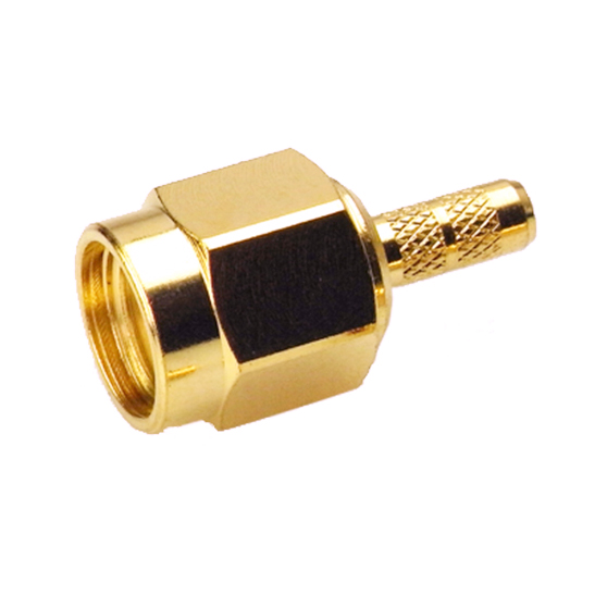
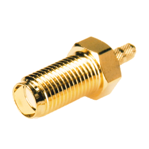
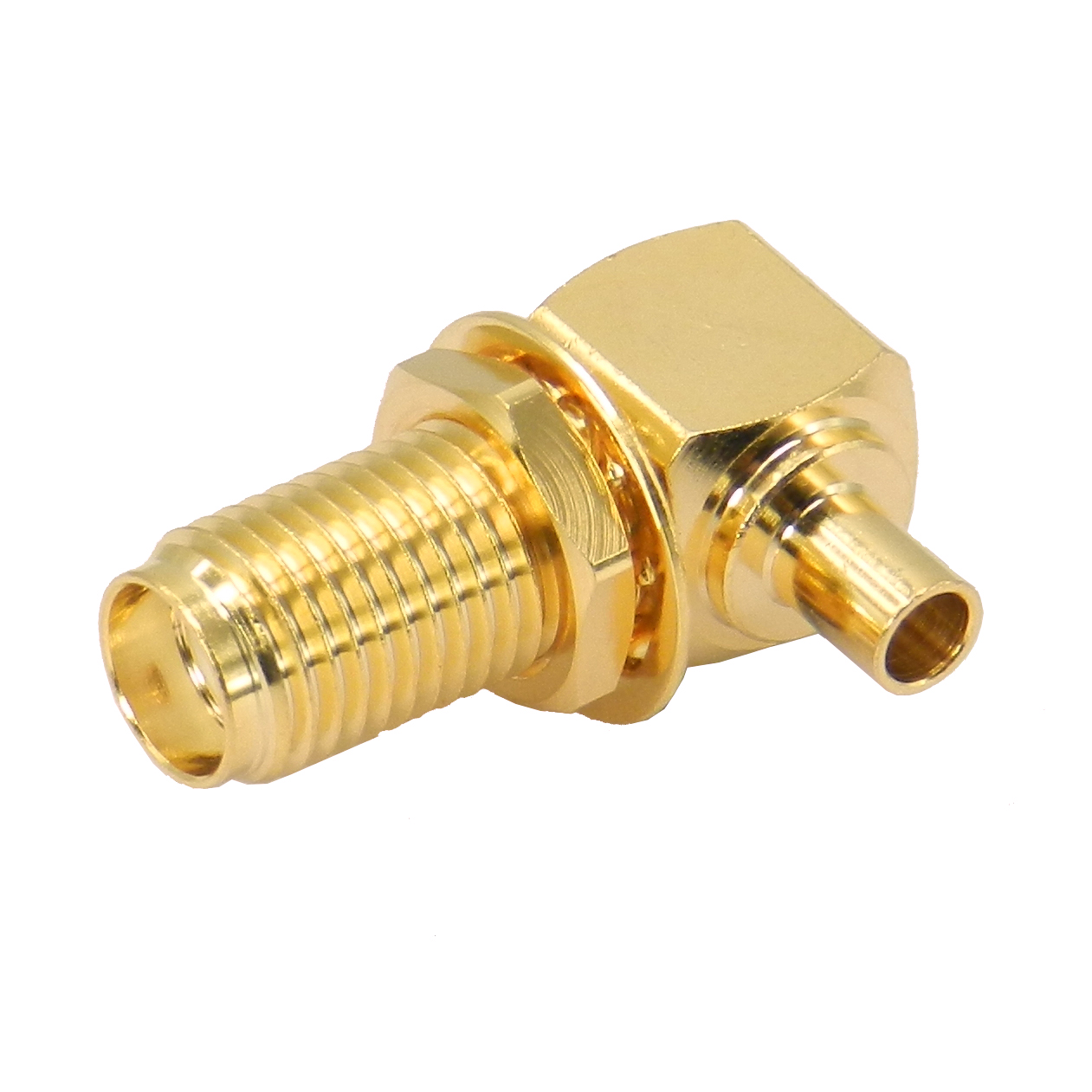
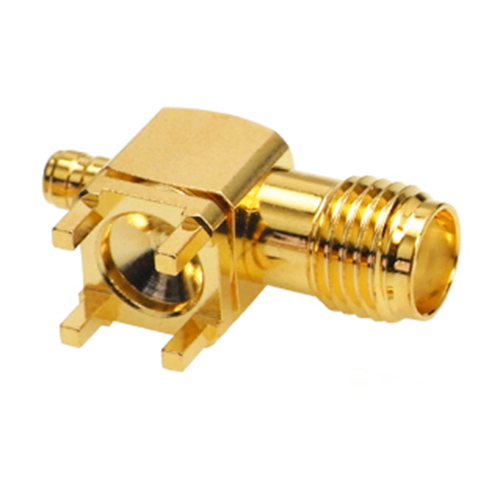
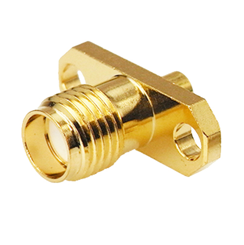
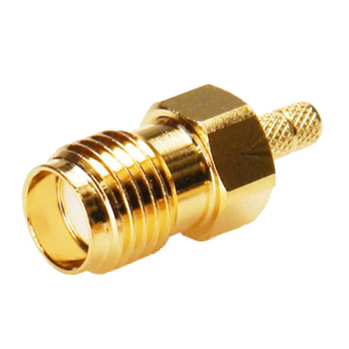
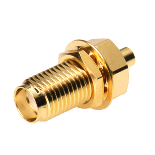
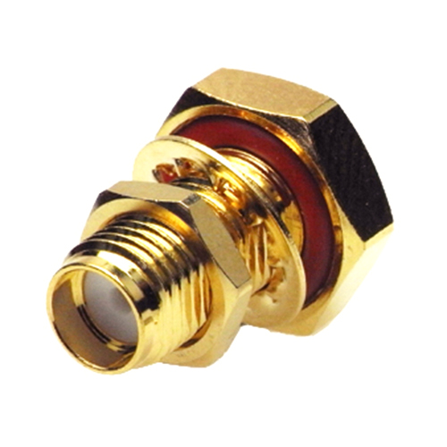
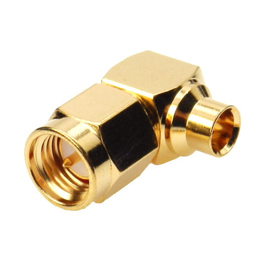
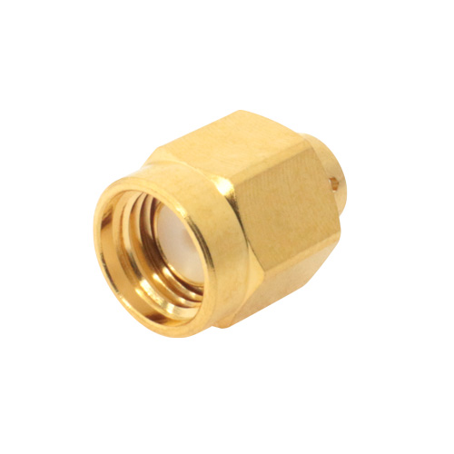
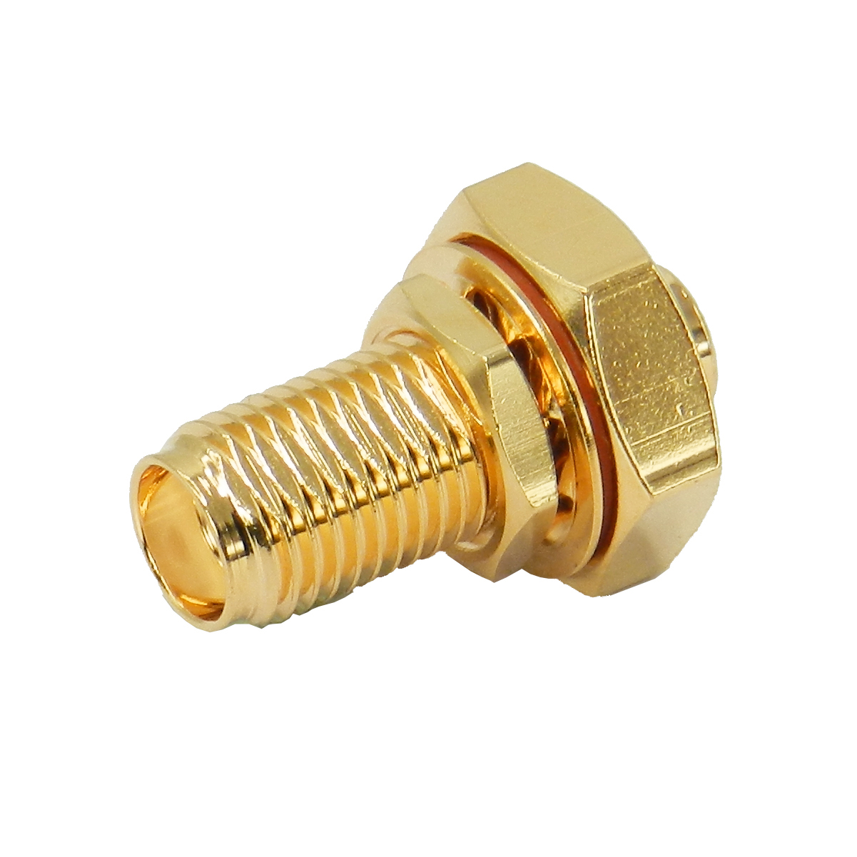
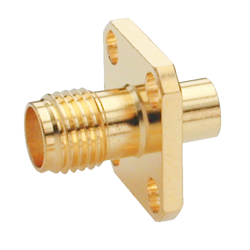
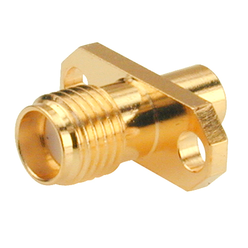
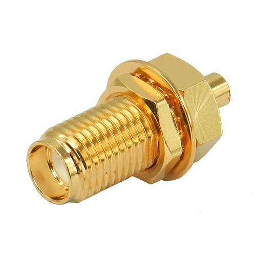
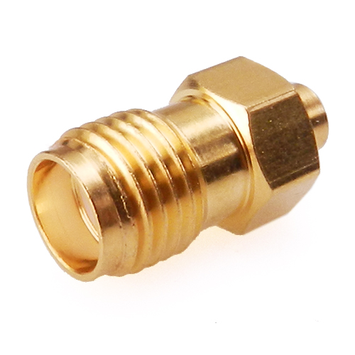
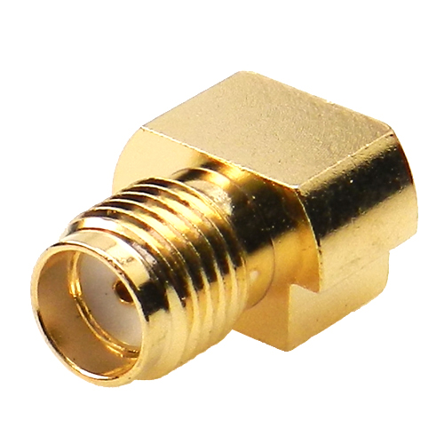
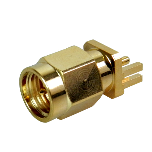
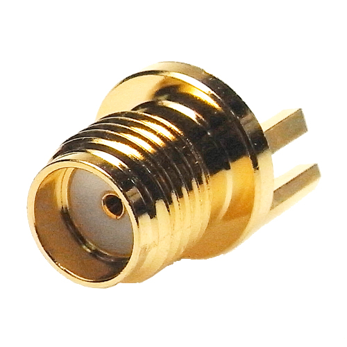
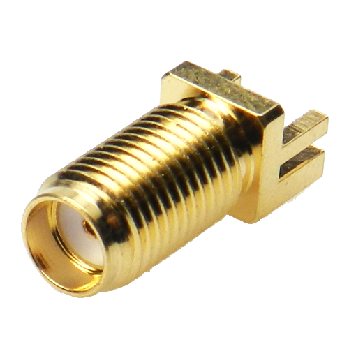
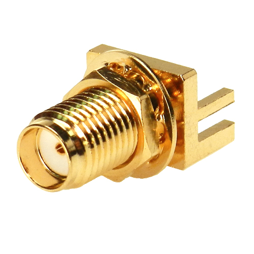
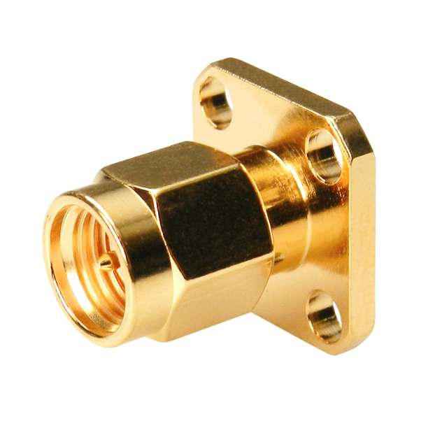
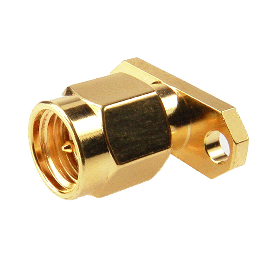
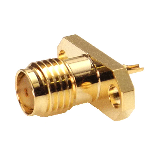
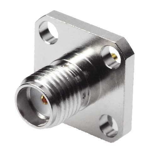
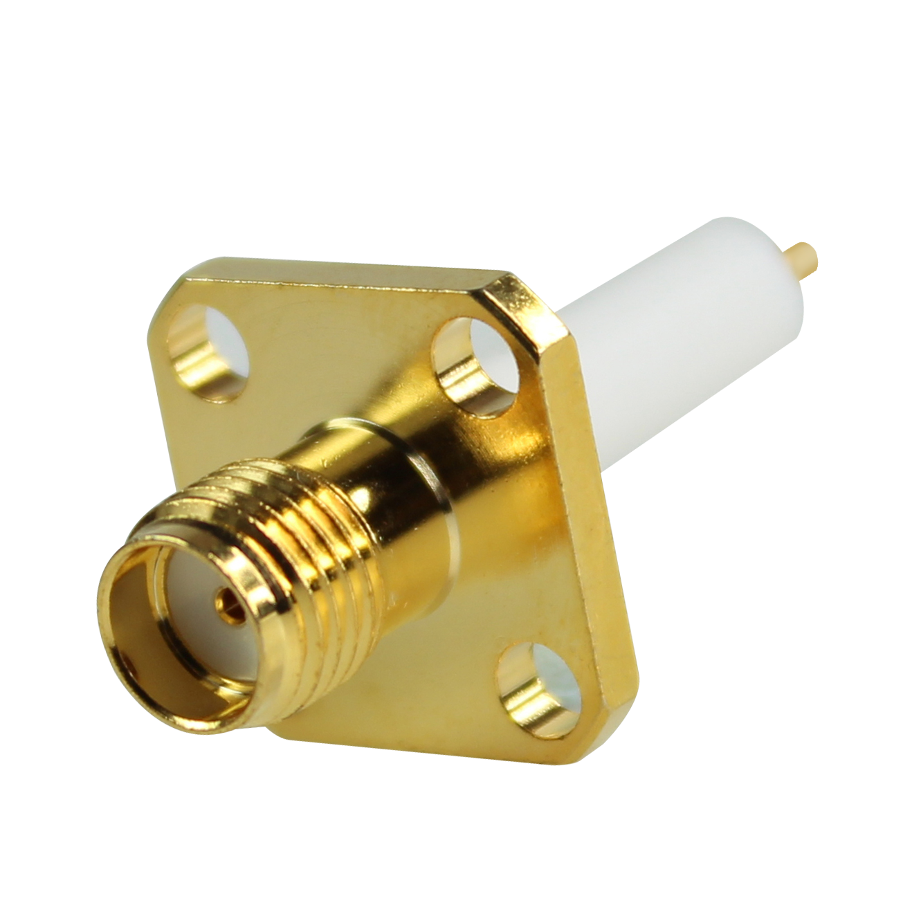
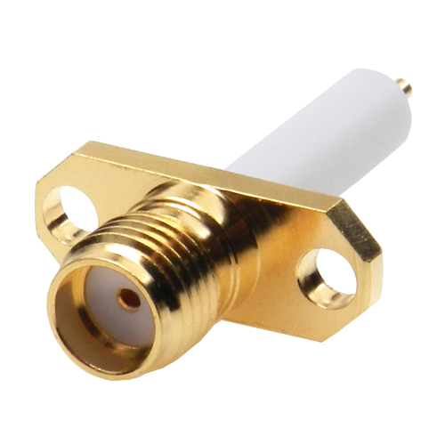
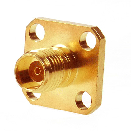
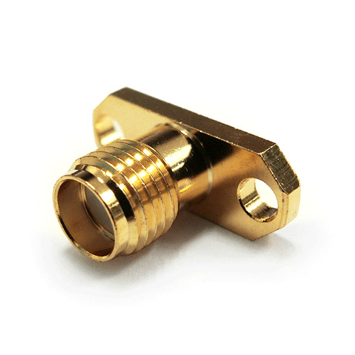
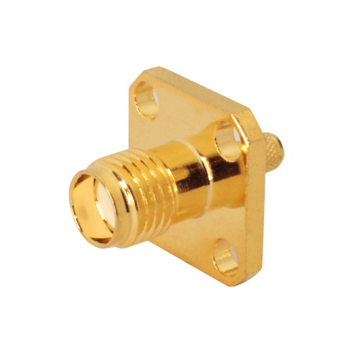
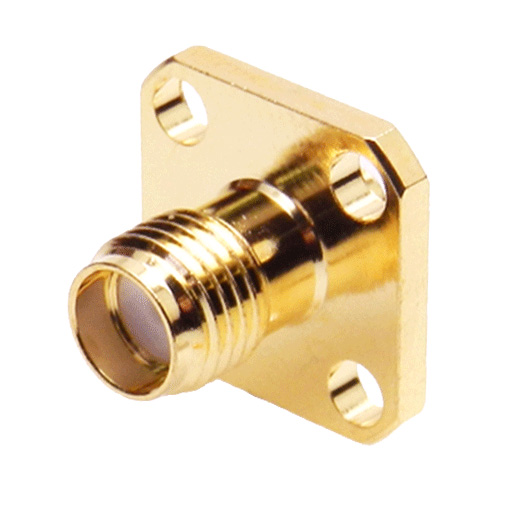
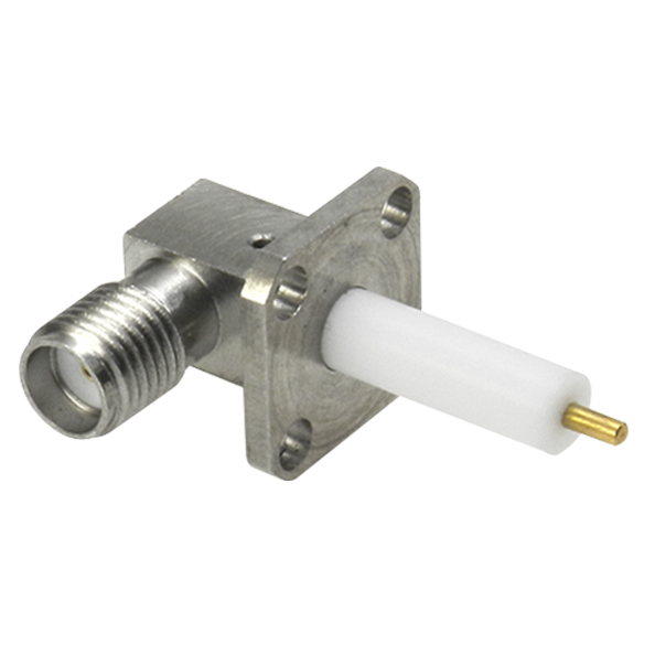
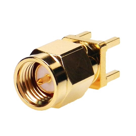
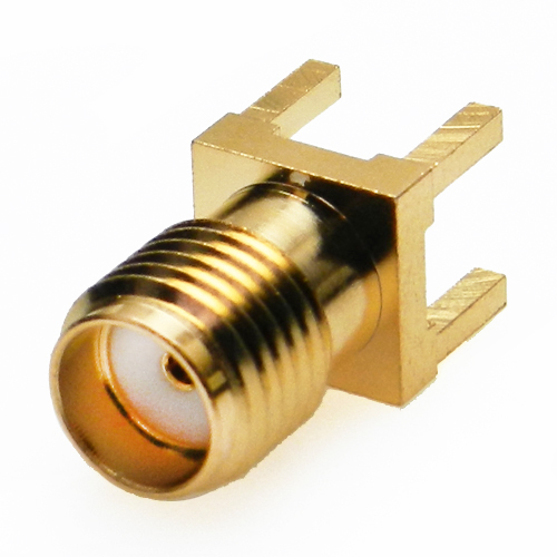
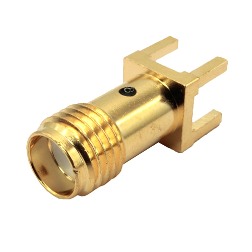
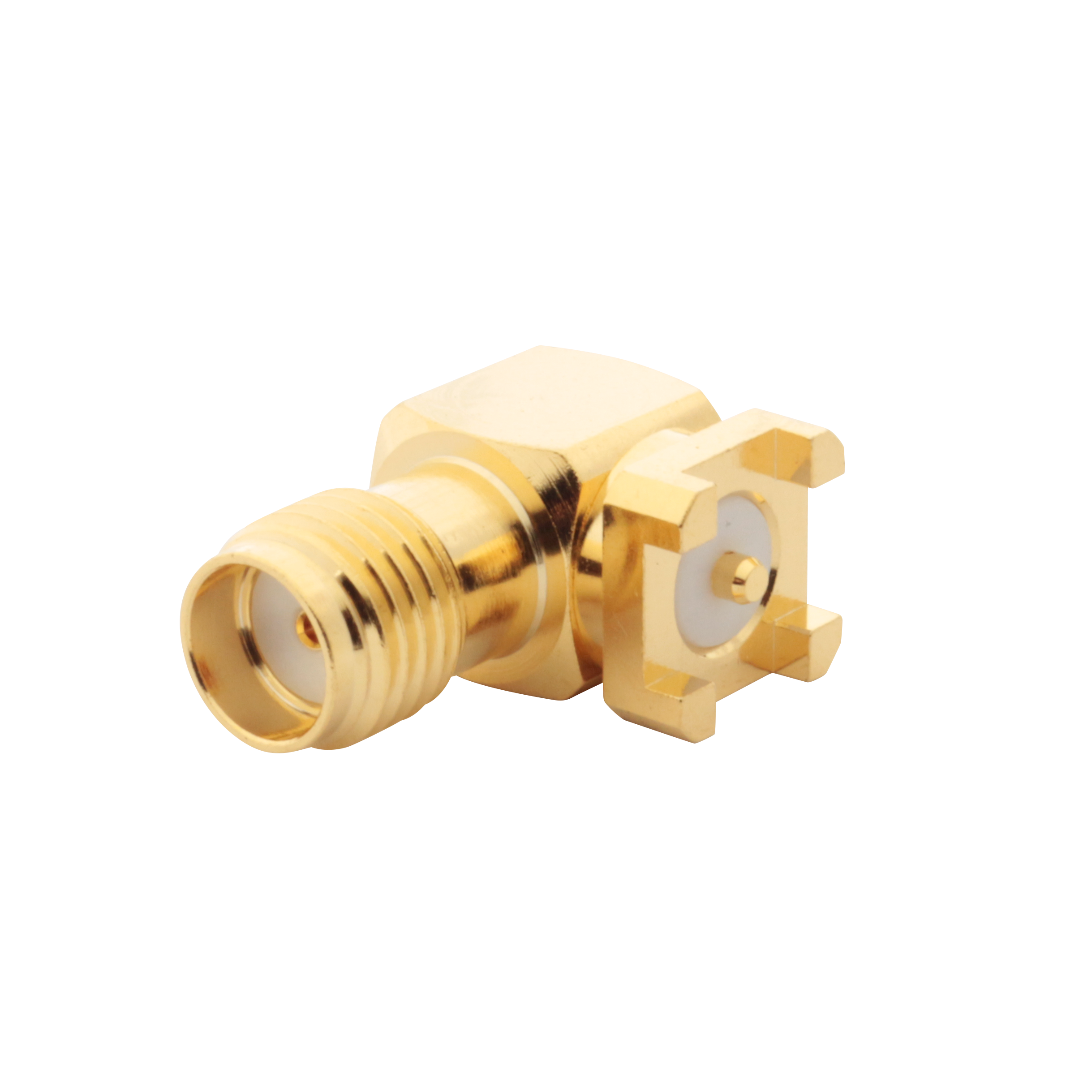
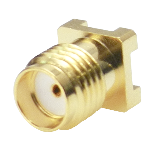
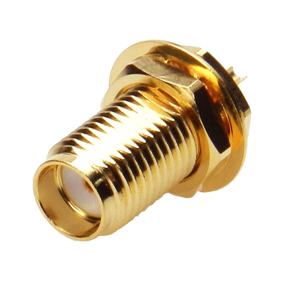
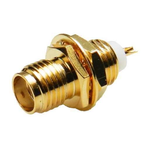
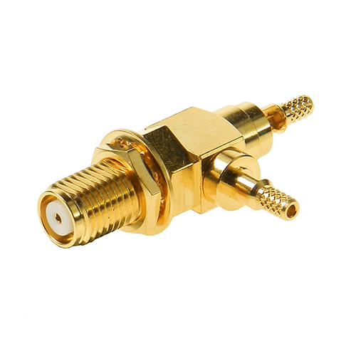
SMA connectors are semi – precision, subminiature devices that provide reliable electrical performance from DC to 12.4 GHz with flexible cable. Semi – rigid cabling extends the frequency range of the device to 18 GHz. These devices offer broadband performance with low reflection and constant 50 ohm impedance. These properties, along with minimum attenuation and low VSWR have made the SMA extremely popular in the microwave community. The SMA design has been broadened to accommodate many interconnect requirements and is available in pressure crimp, clamp and solder terminal attachments. SMA design parameters have incorporated the considerations of balancing cost, size, weight and performance to yield the best value in your microwave system. Among typical applications are components such as dividers, mixers, amplifiers, trimmers and attenuators. SMA connectors are also used to provide interconnections from printed circuit board stripless to coaxial cable.

Applications
- Civil & Military Telecommunication
- Instrumentation
- Wireless
- Process Control
- PC/LAN
- Microwave Components(power splitters and combiners, filters, amplifiers)
Electrical
Impedance:50Ω
Voltage Rating:≥500 V rms (depending on cable)
Insulation Resistance:≥5 GΩ
Dielectric Withstanding Voltage:≥1000 V rms
Contact Resistance:Center Contact ≤3 mΩ、Outer Contact ≤2 mΩ
Features
- Commercial Grade (Brass SMA) available.
- Various cable groups including double shielded RG316.
- Built in accordance with MIL – PRF – 39012F and CECC 22110 / 1111.
- Gold plating or stainless steel passivated finish available.
- Interface according to IEC 169-15, MIL-STD-348B
Mechanical
Mating: 1/4-36 UNS Screw-on Coupling
Force to Engage and Disengage:
Torque: ≦2 in. lbs.
Coupling Proof Torque:≧15 in. lbs.
Coupling Mechanism Retention Rorce:≧60.7 lbs
Environmental
Temperature Range:-65° C to 165° C
Corrosion (Salt Spray):MIL-STD-202, Method 101, Cond. B
Shock :MIL-STD-202, Method 213, Cond. I
Vibration (HF):MIL-STD-202, Method 204, Cond. D
Thermal Shock :MIL-STD-202, Method 107, Cond. B
Except Test High Temperature Shall Be +85°C.