
U250
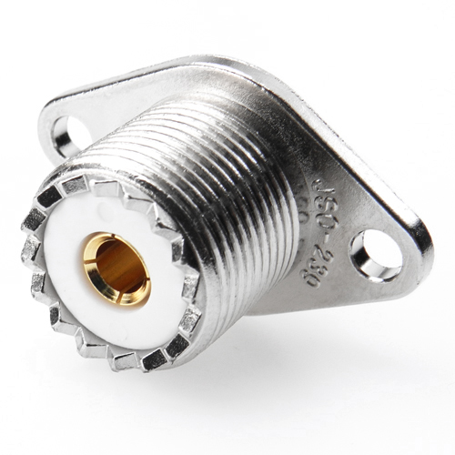
Description
UHF P/M 2-Hole Jack, Receptacle
Cable: N/A
| Applications |
- CB Radios
- Antennas
- Public Address Systems
| Features |
- With the use of optional reducers, UHF connectors are designed to accommodate a wide range of popular coaxial cables.
- Available in crimp & twist-on terminations to provide for low cost installation.
| Special Notice |
• Any questions, please feel free to contact our QA department.
| Electrical |
|
Impedance |
Non-constant |
|
Frequency Range |
0 to 300 GHz |
|
VSWR |
≤1.5 |
|
RF Leakage |
≥90 dB |
|
Dielectric Withstanding Voltage |
2000 V rms |
|
Voltage Rating |
≥750 V rms (depending on cable) |
|
Center Contact Resistance |
≤5 mΩ |
|
Outer Contact Resistance |
≤5 mΩ |
|
Insulation Resistance |
≥5 GΩ |
| Mechanical |
|
Mating |
5 / 8-24UNEF Screw-on Coupling |
|
Connector Durability |
≥500 Cycles (for beryllium copper female contact only) |
|
Cable Retention Force |
≥ 12.1 lbs (for RG316) |
| Environmental |
|
Temperature Range |
-25° C to 70° C |
|
Corrosion (Salt Spray) |
MIL-STD-202, Method 101, Cond. B |
|
Vibration |
MIL-STD-202, Method 204, Cond. B |
|
Thermal Shock |
MIL-STD-202, Method 107, Cond. B |
|
Mechanical Shock |
MIL-STD-202, Method 213, Cond. G |
| Material |
|
Parts Name |
Material |
Plating |
|
Body |
Brass |
Nickel or Silver |
|
Center Contact |
Male: Brass |
Nickel,Silver or Gold |
|
Insulator |
PTFE, Delrin or Bakelite |
None |
|
Gasket |
Rubber |
None |
|
Crimp Ferrule |
Annealed Copper |
Same as Body |
Note: Other Material/Finish is Available on Request.